
Inventor to Revit
Autodesk have enhanced some already fantastic tools that allow us to work with Inventor and Revit together. We have been able to export our Inventor designs, such as light fittings or plumbing fixtures, out for a while now using the BIM Content tool, however we can also export our designs directly as Revit files to be linked into a larger Revit Project. This is especially useful for businesses such as kitchen fitters or joiners, where you are working to bespoke dimensions.
Using Inventor’s AnyCAD functionality and the Interoperability tools, you can import a Revit file into Inventor to use as a reference model, and then design your product or constrain your product to the correct location using that imported geometry.
For our example today, we will be using an office floorplan and adding in a bespoke shelving unit.
The standard workflow is as follows:
- Create 3D view in Revit to be imported into Inventor.
- Import Revit 3D view in Inventor and reduce the complexity of the view.
- Create or import Inventor design using Revit geometry as a reference.
- Export Inventor design out to Revit.
- Import Inventor design into Revit.
Repeat steps 1-5 to make more adjustments to the same project.

1. Create 3D view in Revit.
We require a 3D Revit view, which we need to simplify down to only include the required geometry. In the example above, we have removed the rest of the building and only included the space where we will be installing the shelving unit, as well as any office furniture that has the potential to get in the way.
2. Import Revit 3D view in Inventor.
In Inventor, open a blank assembly. In the Assemble tab click the Place dropdown and then select Place Imported CAD Files. Navigate to the Revit project and open it. This brings up the AnyCAD Import Window. Keep the file as a Reference Model and select the specific 3D view from the drop-down menu. You can further reduce the number of elements by unselecting specific categories. Press OK.

Right click, and select Place Grounded at Origin. This is a very important step, as it will ensure that your Inventor model is designed in the correct location. When you export the model out to be used in Revit, the Inventor model will automatically be positioned in the correct location relative to the reference geometry.

We now have our Revit view in Inventor. We can further reduce the complexity of the model by expanding the Revit model and toggling off the visibility of objects that aren’t required in the view. We have toggled off more furniture that is not required in the design.

3. Create or import Inventor design using Revit geometry as a reference.
We can now leverage Inventor’s powerful modelling capabilities to create our bespoke shelving unit. We will use Inventor’s Frame Generator to create the structure of our shelving unit, whilst using the walls to shape our design. You can use the Assembly to create annotated drawings or presentations for installation or fabrication instructions, which includes the referenced Revit model.

4. Export Inventor design out to Revit.
Now that we have the shelving unit designed in Inventor, we can use our export tools to export this file as an IFC or RVT model, which we can then import into our Revit project. We first need to hide the reference model by right clicking on it and toggling off the visibility. Select File > Export > RVT. This will bring up the simplification Tool, and you will see that the output type already has Revit Model selected.

When exporting files to Revit, it is best practice to simplify the model to only include data that is required for the project. If you would like to learn more about the simplification tool, this blog post goes into more detail on all the options available to you. Once you are happy with your simplification, press OK to start the export.
5. Import Inventor design into Revit.
Now that we have exported our Inventor model, we can link it into our original Revit model by going to Insert > Link Revit. You will see that the Revit model is placed precisely in the correct location.

6. The circular workflow.
Quite often changes are made to a project late in the design process, and this can impact a lot of factors. Because there is a live link between the Revit model and the Inventor assembly, any changes to the Revit model will be carried through to the Inventor assembly, unless that link is manually broken. This allows us to utilise the parametric capabilities of Inventor to allow our design to automatically update if there are any changes in the Revit Model. We will test this by decreasing the gap between the back wall and the chair of the Revit model. Before doing this, we measured the width of the bespoke shelving unit as 2732 mm, whilst constraining the position of the unit offset at 50 mm from the walls
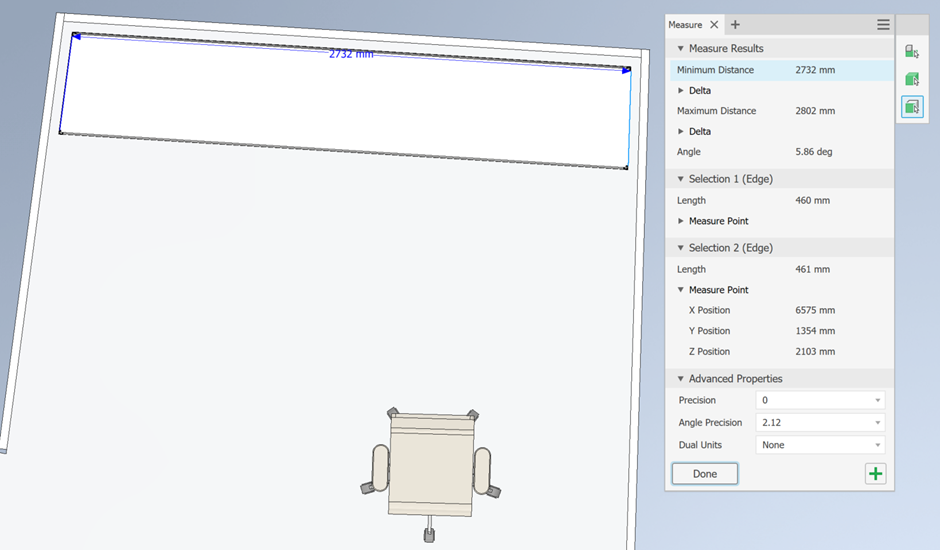
After updating the Revit model, we updated the reference file in Inventor. We can see that the position of the shelving unit is still 50 mm from the walls, and because we used the geometry of the walls to determine the size of the unit, we can see that its width has increased to 2844 mm.


